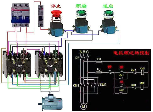
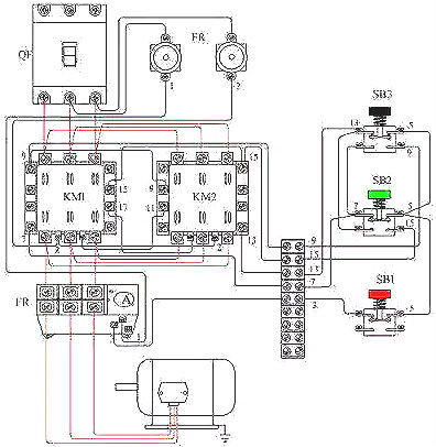
In order to enable the motor to rotate forward and reverse, two contactors KM1 and KM2 can be used to change the phase sequence of the three-phase power supply of the motor, but the two contactors cannot be pulled in. If they are pulled in at the same time, it will cause a short circuit accident of the power supply.
In order to prevent this kind of accident, reliable interlocking shall be adopted in the circuit. The figure below shows the control circuit of motor running in both positive and negative directions with double interlocking of buttons and contactors.
Wiring diagram of three-phase asynchronous motor - actual diagram of positive and negative transfer lines:

To realize the positive and reverse rotation control of the motor, adjust any two phase sequences of its power supply to each other (we call it commutation). Generally, the V phase is unchanged. To ensure that the phase sequence of the motor can be reliably changed when the two contactors act, the upper connection of the contactor shall be consistent during wiring, and the lower connection of the contactor shall be used for phase adjustment. Since the two-phase phase sequence is switched, it is necessary to ensure that the two KM coils cannot be powered on at the same time, otherwise serious interphase short circuit fault will occur, so interlocking must be adopted.
For the sake of safety, the double interlocking positive and reverse control circuit of button interlocking (mechanical) and contactor interlocking (electrical) is often used (as shown in the figure below); Button interlocking is used. Even if the forward and reverse buttons are pressed at the same time, the two contactors for phase modulation cannot be powered on at the same time, which mechanically avoids phase to phase short circuit. In addition, as the applied contactors are interlocked, as long as one of the contactors is powered on, its long closing contact will not be closed. In this way, under the application of mechanical and electrical double interlocking, the motor power supply system cannot be short circuited between phases, effectively protecting the motor, and also avoiding accidents caused by short circuit between phases during phase modulation, burning the contactor.

The main circuit in the figure adopts two contactors, namely positive transfer contactor KM1 and reverse contactor KM2. When the three pairs of main contacts of contactor KM1 are connected, the phase sequence of three-phase power supply is connected to the motor according to U-V-W. When the three pairs of main contacts of contactor KM1 are disconnected and the three pairs of main contacts of contactor KM2 are connected, the phase sequence of the three-phase power supply is connected to the motor according to W-V-U, and the motor rotates in the opposite direction. The circuit requires that contactor KM1 and contactor KM2 cannot be powered on at the same time, otherwise their main contacts will be closed at the same time, causing short circuit of U and W power supplies. Therefore, a pair of auxiliary normally closed contacts of the other side are connected in series in each branch of KM1 and KM2 coils to ensure that the contactors KM1 and KM2 will not be connected to the power supply at the same time. The role of these two pairs of auxiliary normally closed contacts of KM1 and KM2 in the line is called interlocking or interlocking, and the role of these two pairs of auxiliary normally closed contacts in the positive starting process is called interlocking or interlocking contact.
Some common functions:
When selecting a circuit breaker, we should not only pay attention to the main indicators such as the delay curve of the circuit breaker, but also pay attention to its many secondary functions. These often overlooked properties can not only add to a good design, but also help engineers design sophisticated protection circuits for their applications.
At present, there are many circuit breakers equipped with various optional functions on the market, which are very helpful for circuit protection design.
1. Auxiliary contacts (auxiliary switches): they are electrically isolated contacts from the main contacts, and are applicable to alarm and program switches. The auxiliary contact can be used to alarm the operator or control system, send an alarm, or connect the standby power supply in important applications.
2. Transmission: The selection of transmission type is not only for aesthetic reasons. A circuit breaker with a drive rocker switch whose switching speed is twice that of the on/off switch can save cost and circuit board space. Push pull transmission is most stable in case of emergency.
3. Shunt terminals: traditional circuit breakers are considered as "series tripping", because contacts, current sensing elements and loads are all in series. Shunt terminals branch out from the main circuit, so that secondary loads can be connected. If the primary load is short circuited or overloaded, the circuit breaker will trip and cut off the power supply of both loads.
Unlike the auxiliary contact, the shunt terminal is connected to the current carrying path of the circuit breaker between the switch contact and the current sensing element, which means that the second load is not protected from overload or short circuit. An independent circuit breaker can be used to protect the secondary circuit, otherwise the circuit can only be used for equipment with built-in protection circuit.
4. Duplex control (remote tripping or relay tripping): Duplex control circuit breaker combines two electrically isolated inductive elements to achieve multiple functions. For example, the multiple control circuit breaker can use remote control driver or inductor to carry out traditional over-current protection and circuit disconnection. Remote tripping is an example of multiple control, often referred to as "relay tripping".
5. Low voltage trip: This is an independent voltage sensing element in the circuit breaker. If the voltage drops below the preset value, it will open the main contact. Switching circuit breakers with low-voltage tripping are widely used for on/off control of wired connected electrical appliances. The safety management department requires that the power of these appliances must be cut off in case of power failure to avoid the danger of sudden restart of appliances when the power is restored.
6. Automatic tripping: An automatic tripping circuit breaker will not remain closed during a fault - because the switchgear will not fail by forcing the actuator to be on. In a fully automatic trip design, when the actuator is held in the "ON" position, the main contact will always remain open after a fault. Some circuit breakers, which are called "cyclic automatic tripping", cannot be forced to remain connected during a fault, but if the driver is always in the "ON" position, they will be periodically connected and disconnected. If the circuit breaker is installed in an easily accessible place (i.e. not closed), the automatic trip circuit breaker shall be used.
7. Automatic reset: For applications where the circuit breaker is hard to reach, the circuit breaker that automatically resets after the cooling period is a good choice. At this time, if the equipment that can be restarted automatically is specified, there is a great possibility of danger.


